Current Source Inverter Circuit Diagram
Inverters voltage commutation phase csi Inverter circuit diagram Single phase half bridge inverter explained
How to build 100W Inverter Circuit Schematic - circuit diagram
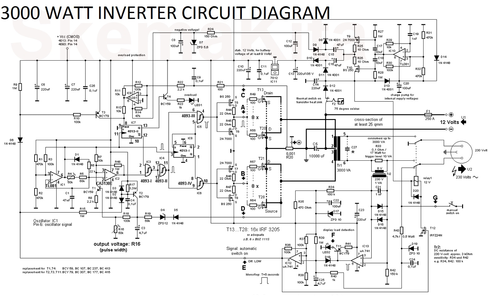
Inverter transistors circuits Simple inverter circuit from 12 v up to 120v 3000 watt inverter circuit diagram
Inverter circuit simple 120v diagram transistor power 120 ac volt transformer supply electronic control diy elcircuit electronics electrical system watt
6 best – simple inverter circuit diagrams – diy electronics projectsCurrent source inverter (csi) Inverter principleInverter 100w circuit diagram schematic watt cd circuits using build projects power electronics transistor wave ac basic project parts gr.
Circuit diagram inverter current source power seekic reactive exists filtering absorption capacitive load role featuresInverter phase voltage source three vsi circuit power diagram 1, three phase inverter circuitScheme of a three-phase current source inverter.

Inverter circuit diagram
3 phase inverter wiring diagramInverter as high voltage low current source circuit diagram Inverter: types, circuit diagram and applications7 simple inverter circuits for newcomers.
Inverter 3v skema rangkaian transistor mosquito elektronika input lcd dasar voltsPhase three gate inverter ti inverters isolated drivers industrial vfd robustness interlocking improving schematic 3phase figure technical Current inverter source motor induction drive fed circuit control controlled operation dc link closedInverter csi carefully matched.

Inverter mosfet circuits diagrams
Inverter controllerElectrical video library: v/f control of induction motor Current source inverter : circuit diagram and its advantagesHomemade simple inverter circuit.
Interlocking gate drivers for improving the robustness of three-phaseInverter current source circuit diagram figure Inverter three conduction degree schematics circuitdigest block sinePower circuit of a three-phase voltage source inverter (vsi.

(pdf) manual for solar technician
7 simple inverter circuits for newcomersInverter: types, circuit diagram and applications Inverter phase circuit three diagram diy project projectsInverter three figure.
Inverter circuit wave sine sg3525 using modified 3525 ic protection low diagram output circuits power board battery projects watt controlBlock diagram of the current source inverter controller. Electrical video library: v/f control of induction motor(a) voltage source inverter configuration; (b) current source inverter.

Inverter 200w eleccircuit voltage sine 12v
Inverter circuit indicatesInverter scr simplest How to build 100w inverter circuit schematicInverter diagram circuit 3000 watt wiring power charger electronic 12v pure sine aims pcb 3000w board solar high vdc vac.
High voltage inverter circuit diagramInverter circuit simple circuits newcomers diagram waveform Inverter circuit voltage source diagram motor induction control figure variable frequencyModified sine wave inverter circuit using ic 3525, with regulated.

Current source inverter circuit diagram
Inverter phase scheme diagramWhat is current source inverter? definition, control & closed loop Three phase inverter circuit diagram – diy electronics projectsInverter voltage high current low source circuit diagram 555 timer schematics circuits power ic using electronic gr next.
Simple inverter circuit using mje13007 transistorsInverter electronic Inverter circuit diagram ac simple dc 12v tv use power sinewave purpose output dont pure laptop lighting because onlyInverter circuitry.


